Direct Current
Voltage is what makes electrons flow, and when they flow in one direction we call it direct current.
People have found it helpful to think of electricity as a fluid that flows along a wire. Voltage is like a pressure, pushing that fluid along. We now know it’s not a fluid, but when it flows we still call it a current. When this current flows through a wire a pretty astounding thing happens. It immediately forms a magnetic field around the wire. Magnetism is as mysterious as electricity; it shouldn’t surprise us that the two are so intertwined, but there you have it.
Current
In 1820, just 20 years after Volta discovered his battery, a Danish physicist named Hans Christian Ørsted published a paper describing the results of his latest experiment. Ørsted had been working with, and improving upon, Volta’s battery since it’s publication. His paper described how a compass needle would deflect perpendicularly to a wire that was carrying an electric current. The importance of this discovery was recognized by many of his peers, including a French mathematics professor and physicist named André-Marie Ampère. Like many important discoverers of electrical phenomenon during that period, Ørsted has a unit named after him; the SI unit of measure for a magnetic field is the Ørsted.
Upon hearing of Ørsted’s experiment Ampère set out to repeat it, and to discover a theory to explain the results. He was able to show that two parallel wires with current flowing through them in the same direction attracted each other, while they repelled each other if the current in one of them was reversed. This proved that the magnetic effect was solely from the current; there were no longer any permanent magnets involved. This link between electricity and magnetism he called electrodynamics. In 1826 he published his mathematical derivation of a force law showing the relationship between a static current and the force of the magnetic field it produces. In his honor the measure of electrical current is called the Ampere, or simply Amp, with the abbreviation A.
While the theoretical principles of electrodynamics were being established, there were some immediate practical consequences. By putting a magnetized needle over a coil in series with a wire, the deflection of the needle can be used to measure the current in the wire. This device was called the Galvanometer (for Luigi Galvani).
Resistance
With the ability to now measure both voltage and current Georg Ohm set out to discover the relationship of different lengths of wire on both. He was a mathematician in Germany trying to apply mathematics to experimental work in order to get a university post. He published his work in 1826, along with methods of measurement and a mathematical treatment of his empirical data. The result is what we know as Ohm’s Law: the voltage across a resistance is proportional to that resistance and the current through it.
Or more succinctly:
V = I * R
where V is the voltage (in volts), I is the current (in amps), and R is the resistance in, you’ve probably guessed it, ohms. The symbol for ohms is written Ω.
A resistor is a wire that has been stretched to a specific diameter to form a certain resistance. There is usually a ceramic coating around the wire to dissipate heat, and a lead coming out of each end. The resistor is painted with colored bands on the ceramic coating to indicate the resistance value. Resistors are useful for changing the voltage and/or current of a circuit for specific effects. In the US, the symbol for a resistor is a squiggly line with the resistance printed next to it.
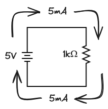
With a battery of 5V across a resistor of 1kΩ the circuit will have a current of 5mA flowing through it ( 5V / 1000Ω = 0.005A = 5mA). Notice how the direction of the current is shown as going from the positive terminal of the battery to the negative. For nearly a 100 years people thought that it was positively charged particles flowing from the positive terminal to the negative. We now know that it’s negatively charged electrons that flow, but much of the notation has remained. This “positively” flowing current is referred to as conventional current, and is it the default used in most circuit schematics.
While Ohm’s Law is quite useful, it has it’s limits. You may have a battery that can’t supply 10A of current for example, so it doesn’t matter what you make the resistance you’ll never get the current that high. In fact, all batteries have something called capacity. A 9V alkaline battery has a capacity of 600mAh which means if you draw 10mA from it, you can do so for 60 hours before it’s dead. The voltage will actually decrease quite a bit before the manufacturer considers it “dead”. This is also a maximum capacity, and the more current you draw the less the actual capacity. For example, if you draw 50mA, the capacity ends up being closer to 400mAh. Drawing more than 50mA can damage the battery. This also depends on temperature, age of the battery, how often it’s used, etc. but the point is that all batteries have a limited capacity.
DC Circuits
Like Ohm, Gustov Kirchhoff was a German mathematician and physicist working on electricity. In 1847, he extended Ohm’s Law with two additional laws that help us to analyze the current and resistance of more complicated circuits. These are known as Kirchhoff’s Laws:
- The sum of voltage increases and decreases around a closed circuit must sum to zero
- The sum of currents entering and leaving a node must sum to zero
Series Circuits
To see how useful this is in applying Ohm’s Law, consider a circuit with two resistors connected in a single path, or in series.
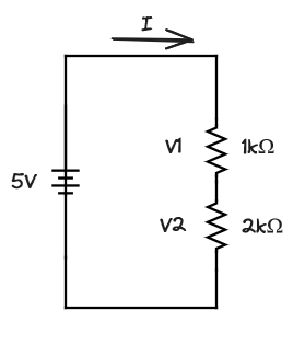
We know the battery is 5V and the first resistor is 1kΩ and the second is 2kΩ. What’s the current I and the voltage drop across each resistor (V1 and V2)? First off, we know the current I is the same through both resistors because of the second law above: there are no other paths for the current to go. This means we can write the voltage drops across each resistor using Ohm’s Law as:
V1 = I * 1000
V2 = I * 2000
If we add those two equations together we get:
V1 + V2 = (I * 1000) + (I * 2000) = I * (1000 + 2000)
From the first law we also know that the total voltage drop across both resistors (V1 + V2) must be 5V, because the battery is 5V. So:
5 = I * (1000 + 2000)
This means the current I must be 5 / 3000 which is about 1.7mA. We can then get V1 = 0.0017 * 1000 = 1.7V and V2 = 0.0017 * 2000 = 3.4V. We’ve rounded, but these values will be pretty close.
The interesting part is that we added the two resistors together to get the total resistance: R = 1000 + 2000. When resistors are in series we can add them together to get the total resistance.
Parallel Circuits
What if the resistors are not in series (end-to-end) but in parallel (next to each other)?
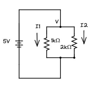
Now the current through each resistor will be different (I1 and I2) but the voltage across them is the same (V = 5V). Using Ohm’s law for each we can write:
V = I1 * 1000
I1 = V / 1000

V = I2 * 2000
I2 = V / 2000
We also know that the total resistance (R) whatever it is, when multiplied by I1 + I2 will give us the voltage drop V. By substituting the values above for I1 and I2:
V = R * (I1 + I2)
V = R * ((V / 1000) + (V / 2000))
But the V cancels out:
1 = R * ((1 / 1000) + 1 / 2000)
or
1 / R = 1 / 1000 + 1 / 2000
This is interesting. We don’t know what the total resistance R is, but we know what 1 / R is. It’s 1 / R1 + 1 / R2, or 1 / 1000 + 1 / 2000 = 0.0015. This is 1 / R, so R is the reciprocal of 0.0015, which is about 667Ω. To get the total resistance of more resistors in parallel we would continue to add their reciprocals, eg 1 / R1 + 1 / R2 + 1 / R3 etc. and then take the reciprocal of the sum.
Getting the total resistance is more challenging than getting the individual currents, which we can do by just using Ohm’s law.
  V = I * R
  5 = I1 * 1000
  I1 = 5 / 1000 = 5mA

  and

  5 = I2 * 2000
  I2 = 5 / 2000 = 2.5mA
We can compare this to what we get by using the total resistance, R = 667Ω.
V = I * R
5 = I * 667
I = 5 / 667 = 7.5mA (rounding)
With just these laws we can analyze circuits with an arbitrary number of loops and branches, at least for circuits made up of resistors. There are other components that make circuits more interesting, like capacitors, inductors, and semi-conductors. But those are a topic for another day. There is one last thing to cover with these simple circuits.
Electronic Switches
Switches are so common we don’t often think of them as a type of component, but they are critical. At it’s simplest a switch is used to either open or close a circuit path. When combined they can perform logic functions. There are lots of symbols for switches. Two common ones are shown below: a normally open (no) push button switch (S1), and a toggle switch (S2).
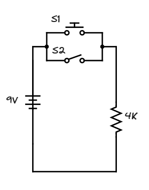
The switch S1 has a spring that keeps it open until you press it, closing the contacts. The switch S2 slides either open or closed. Since these switches are in parallel, closing either switch will allow current to flow through the resistor. The S2 switch acts as as an “enable” switch for S1: in order for the S1 button pushes to matter, S2 must be open.
In 1830 a man named Joseph Henry was wrapping coils of wire around iron bars to make magnets, electromagnets. While he wasn’t the first to make an electromagnet, he, along with Michael Faraday, both independently discovered the property of mutual inductance while experimenting with electromagnets. Inductance is the resistance of a current to change in the presence of a magnetic field, and that a magnetic field can induce a current to move in a coil. Mutual inductance occurs when the magnetic field from one coil is used to induce a current in another coil. This was another major step forward in the emerging field of electromagnetics. Faraday was the one to publish the results, but both men have units named after them: the Farad is a unit of capacitance, the Henry is the unit of inductance.
By 1835 Henry had created a unique application for electromagnets. He used the force of the magnet to activate a switch. This seemingly simple idea has some interesting ramifications. It means you don’t need a finger near the switch in order to turn it on or off, you can now do it from a distance. What’s more, the switch can be on an entirely different circuit than the electromagnet. The only thing they share is a magnetic field. By 1860 this device would be known as a relay.
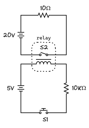
The circuit with S1 will cause 5mA to flow through the 10KΩ resister when closed. This current will flow through the coil and cause the switch S2, which is part of the relay, to close. When S2 closes it will cause the much larger current of 2A to flow through the 10Ω resistor, assuming the battery has enough capacity (like a lead-acid car battery).
The important point is that a circuit with a small current can turn another circuit with a much larger current on and off. And it can do this from a distance. The switch S1 doesn’t have to be near the coil.
What’s the point?
Everything in this post is state-of-the-art technology circa 1840, and that was the decade where the world started getting much smaller. It may not seem like you can do much with batteries, wires and electronic switches, but it turns out that’s all you need to build a communication network.